
AC | DC | Signal properties | RMS | PWM
Next Page: Oscilloscopes (CROs)
Also See: Diodes | Power Supplies
AC means Alternating Current and DC means Direct Current. AC and DC are also used when referring to voltages and electrical signals which are not currents! For example: a 12V AC power supply has an alternating voltage (which will make an alternating current flow).
An electrical signal is a voltage or current which conveys information, usually it means a voltage. The term can be used for any voltage or current in a circuit.
Alternating Current (AC) flows one way, then the other way, continually reversing direction.
An AC voltage is continually changing between positive (+) and negative (-).
The rate of changing direction is called the frequency of the AC and it is measured in hertz (Hz) which is the number of forwards-backwards cycles per second.
Mains electricity in the UK has a frequency of 50Hz.
See below for more details of signal properties.
An AC supply is suitable for powering some devices such as lamps and heaters but almost all electronic circuits require a steady DC supply (see below).

AC from a power supply
This shape is called a sine wave.

This triangular signal is AC because it changes
between positive (+) and negative (-).
Direct Current (DC) always flows in the same direction, but it may increase and decrease.
A DC voltage is always positive (or always negative), but it may increase and decrease.
Electronic circuits normally require a steady DC supply which is constant at one value or a smooth DC supply which has only a small variation called ripple.
Cells, batteries and regulated power supplies provide steady DC which is ideal for electronic circuits.
Power supplies contain a transformer which converts the mains AC supply to a safe low voltage AC. Then the AC is converted to DC by a bridge rectifier but the output is varying DC which is unsuitable for electronic circuits.
Some power supplies include a capacitor to provide smooth DC which is suitable for less-sensitive electronic circuits, including most of the projects on this website.
Lamps, heaters and motors will work with any DC supply.
Please see the power supplies page for further information.
Power supplies are also covered by the Electronics in Meccano website.

Steady DC
from a battery or regulated power supply,
this is ideal for electronic circuits.

Smooth DC
from a smoothed power supply,
this is suitable for some electronics.

Varying DC
from a power supply without smoothing,
this is not suitable for electronics.
An electrical signal is a voltage or current which conveys information, usually it means a voltage. The term can be used for any voltage or current in a circuit.
The voltage-time graph below shows various properties of an electrical signal. In addition to the properties labelled on the graph, there is frequency which is the number of cycles per second.
The diagram shows a sine wave but the properties apply to any signal with a constantly repeating shape.
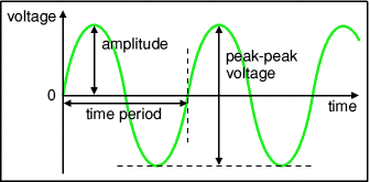
Frequency and time period are the inverse of each other:
| frequency = | 1 |
| time period |
and
| time period = | 1 |
| frequency |
Mains electricity in the UK has a frequency of 50Hz so it has a time period of 1/50 = 0.02s = 20ms.
The value of an AC voltage is continually changing from zero up to the positive peak, through zero to the negative peak and back to zero again. Clearly for most of the time it is less than the peak voltage, so this is not a good measure of its real effect.
Instead we use the root mean square voltage (VRMS) which is 0.7 of the peak voltage (Vpeak):
| VRMS = 0.7 × Vpeak |
and
| Vpeak = 1.4 × VRMS |
These equations also apply to current.
It is important to note that these equations are only true for sine waves (the most common type of AC) because the 0.7 and 1.4 factors are different values for other shapes.

The RMS value is the effective value of a varying voltage or current. It is the equivalent steady DC value which gives the same effect.
For example a lamp connected to a 6V RMS AC supply will light with the same brightness when connected to a steady 6V DC supply. However, the lamp will be dimmer if connected to a 6V peak AC supply because the RMS value of this is only 4.2V (it is equivalent to a steady 4.2V DC).
You may find it helps to think of the RMS value as a sort of average, but please remember that it is NOT really the average! In fact the average voltage (or current) of a typical AC signal is zero because the positive and negative parts exactly cancel out.
AC voltmeters and ammeters show the RMS value of the voltage or current.
If the peak value is meant it should be clearly stated, otherwise assume it is the RMS value. In everyday use AC voltages (and currents) are always given as RMS values because this allows a sensible comparison to be made with steady DC voltages (and currents), such as from a battery.
For example a '6V AC supply' means 6V RMS, the peak voltage is 8.4V. The UK mains supply is 230V AC, this means 230V RMS so the peak voltage of the mains is about 320V.
First square all the values, then find the average (mean) of these square values over a complete cycle, and find the square root of this average. That is the RMS value. Confused? Ignore the maths (it looks more complicated than it really is), just accept that RMS values for voltage and current are a much more useful quantity than peak values.
Pulse Width Modulation (PWM) is the technique of varying the proportion of a digital (on/off) signal which is on or high (the pulse width) to control an analogue quantity such as the brightness of an LED or the speed of a motor.
The pulse width is the mark time (Tm) and the off or low part of the signal is the space time (Ts). The pulse width (Tm) proportion of the complete on/off cycle (Tm + Ts) is called the duty cycle and is usually given as a percentage. The diagram shows examples of 90% (mostly on), 50% (equal on and off times) and 10% (mostly off) duty cycles.
PWM is a useful way to convert a digital signal to an analogue quantity determined by the average time the digital signal is on (or high) over a complete cycle.
The frequency of the on/off pulses must be sufficiently high for the output to appear continuous, for example at low frequencies an LED will simply flicker but at 1kHz (1000 flashes per second) our eyes cannot see the rapid flashes and instead we see an average brightness determined by the duty cycle. For controlling motor speed the frequency can be lower such as 100Hz because mechanical inertia in the system smooths out the pulses.

PWM is a good way to vary the brightness of an LED, for example to create a wide range of colours with an RGB LED. For an example circuit see 555 Astable.
Microcontrollers (such as the Raspberry Pi and Arduino) use PWM to control the speed of motors.
Dimmer switches use a form of PWM to vary the brightness of lights in buildings, in this case the pulses are parts of the AC sine wave of the mains electricity supply.
Next Page: Oscilloscopes (CROs) | Study